Calibration
Propeller Config
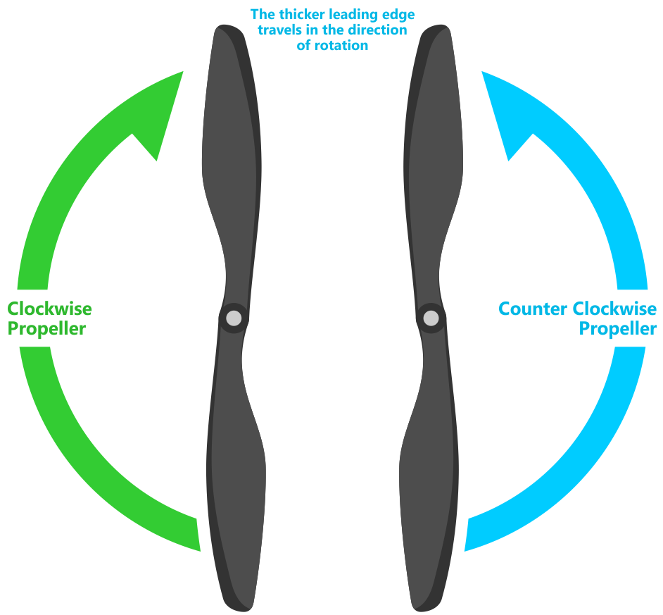
The propellers will become damaged during transport or interactions with vegetation. The propellers should be inspected before flight for cracks, chips, folded edges, and bends. Damaged props are like driving with an unbalanced wheel. It induces vibrations in the vehicle which leads to poor flight performance.
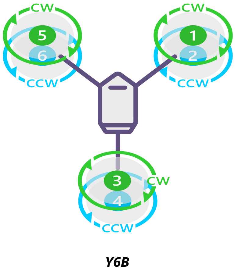
The propellers come in a pair. One that rotates clockwise (CW) labelled R and one counter-clockwise (CCW) labelled L. The CW props are on top and CCW are on bottom. Ensure both propellers are facing up, you should see the text on both propellers when viewing top down.
|
|
Motor Test
If you have changed out motors or switched ESC, it is good to test that you have attached the ESC to the correct port in the Pixhawk and have the correct motor direction.
Mission Planner
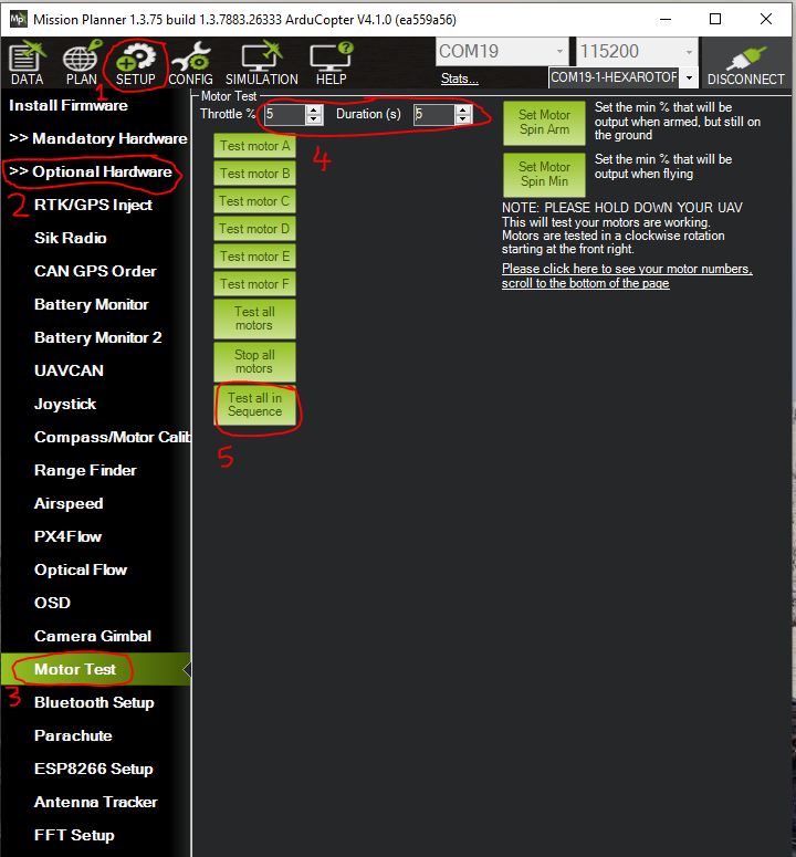
Navigate to Setup > Optional Hardware > Motor Test. Set:
- Throttle
5
- Duration
5
Danger
Incorrect setting of the Throttle and Duration will result in the copter taking off
Select Test all in Sequence
Change any motors that are in the incorrect sequence (see Propeller Config)
Run Test all in Sequence again. If the spin direction is incorrect, swap two of the ESC to motor leads (see Propeller Config)
Run through it once more to ensure you have the correct motor order and spin
Level Calibration
If the HUD is significantly skewed where roll and/or pitch is ±10° when the copter is level it would be good to do a level calibration. This lets the Pixhawk know what level flight should be.
Take the copter off the legs and do calibration on a level, stable, surface such as in the office floor. Plug in the battery and attach the telemetry to your device
QGroundControl
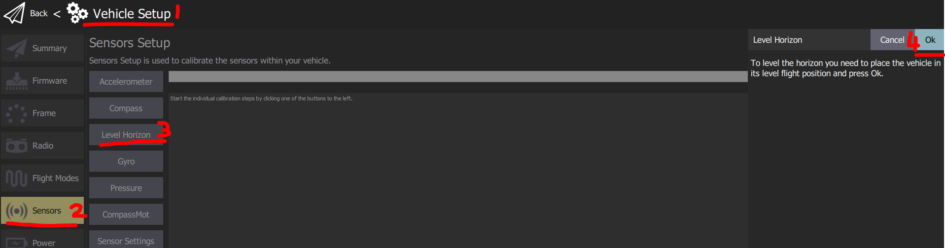
Navigate to Vehicle Setup > Sensors > Level Horizons
Once the copter is level, select Ok.
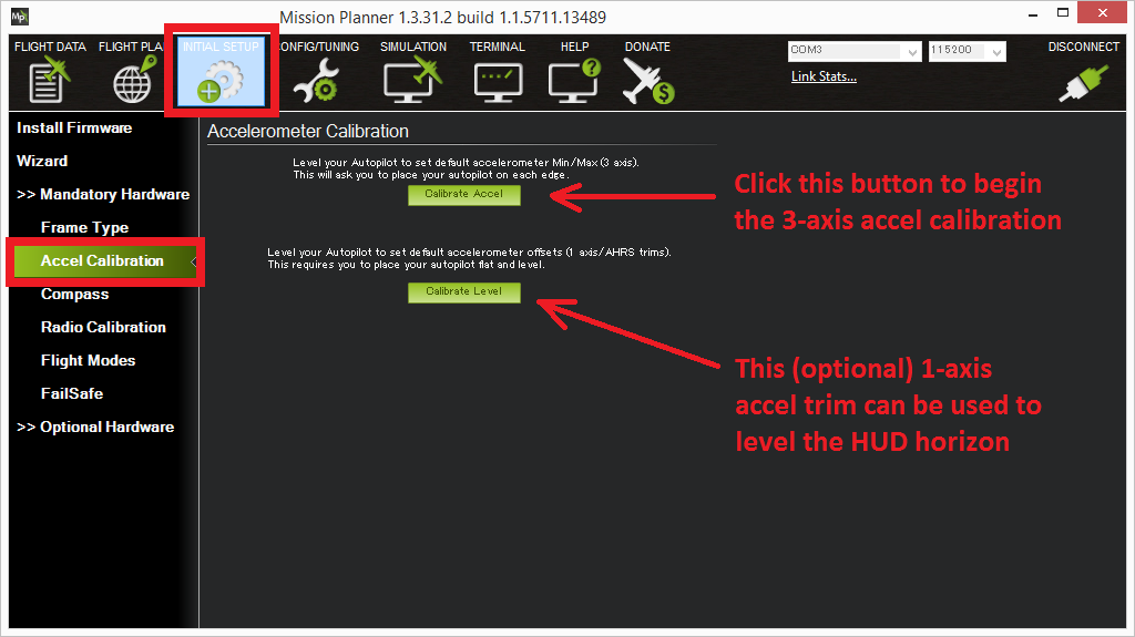
Mission Planner
Navigate to Setup > Mandatory Hardware > Accel Calibration
Once the copter is level, select Calibrate Level
Accelerometer Calibration
If the Pixhawk has been moved it is a good idea to recalibrate the accelerometer, so it knows where the new level is. It will ask you to put the copter in various positions, and to confirm on the device when you have it in position. Calibration is easier with two people, one to position the copter, and one to operate the ground control station.
It is important that the vehicle is kept still immediately after pressing the key for each step. This is more important than getting the angle exactly right. Except for the first “LEVEL”, the positions can be within 20° of being exact. Being still in each position as you press the key is much more important. The level position is the most important to get right as this will be the attitude that your controller considers level while flying.
Take the copter off the legs and do calibration on a level, stable, surface such as in the office.
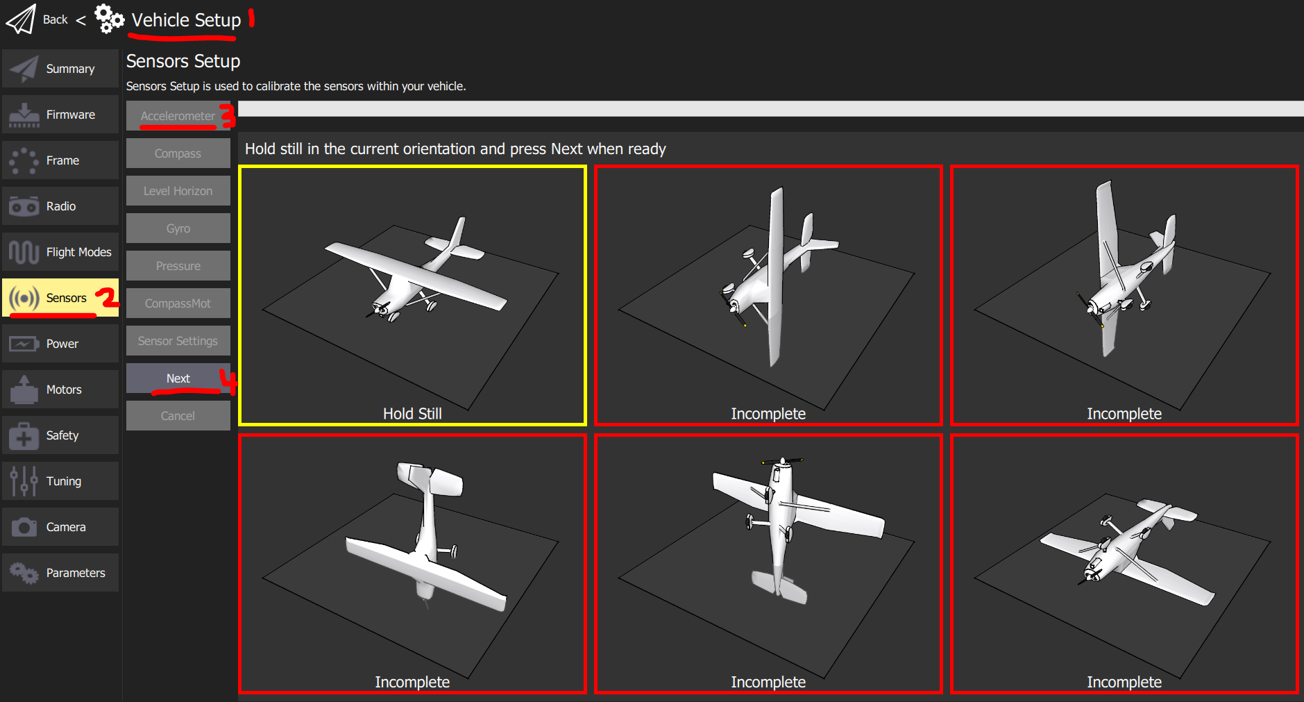
QGroundControl
Navigate to Vehicle Setup > Sensors > Accelerometer
Follow the onscreen prompts. Press Next when the copter is in position.
Mission Planner
Navigate to Setup > Mandatory Hardware > Accel Calibration
Mission Planner will prompt you to place the vehicle each calibration position
Press any key to indicate that the autopilot is in position and then proceed to the next orientation
Proceed through the required positions, using the Click when Done button after each position is reached
When you’ve completed the calibration process, Mission Planner will display “Calibration Successful!”
Compass Calibration
The compass is used to maintain the heading/yaw of the copter in Loiter Mode. If the copter tends to drift in Loiter you may need to calibrate the compass. This procedure is commonly known as doing the drone dance.
The calibration needs to be done outdoors in a spot with good 3D GPS lock. Move away from magnetic disturbances, such as electronics, buildings, vehicles, and large metal objects. It is easiest done with two people, one to manoeuvre the copter and one to read the device. The copter will need to be held in each orientation and do a 360° spin. This can be dizzying so try alternate rotation directions. The internal compass is disabled as it has too much noise resulting in poor compass readings. We will only calibrate the external GPS compass.
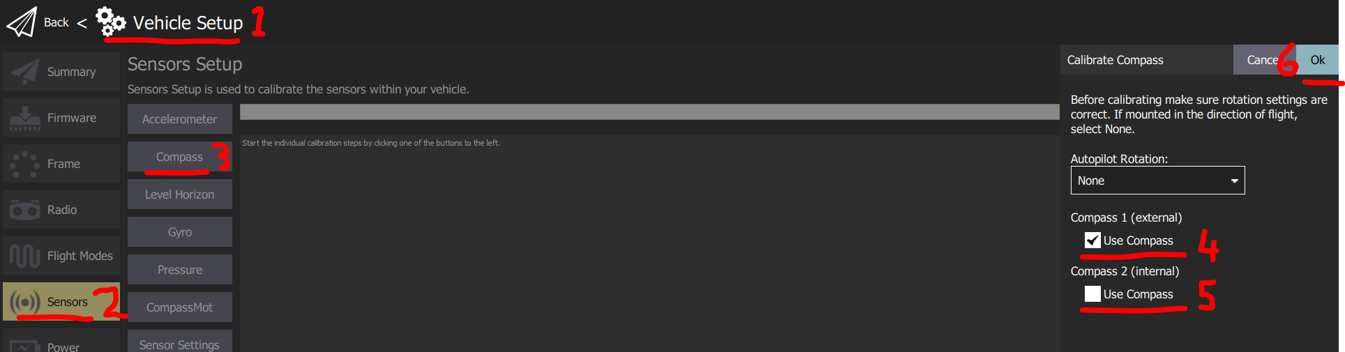
QGroundControl
Navigate to Vehicle Setup > Sensors1 > Compass. Ensure:
- Compass1
☑
- Compass2
☐
Select Ok when ready to rotate the copter
You should hear a single tone followed by short beep once per second
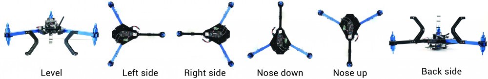
Rotate the vehicle as demonstrated above
Upon successful completion three rising tones will be emitted and a “Please reboot the autopilot” window will appear. Reboot the Pixhawk
Mission Planner
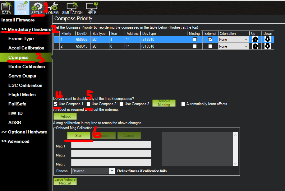
Navigate to SETUP > Mandatory Hardware > Compass. Ensure:
- Use Compass 1
☑
- Use Compass 2
☐
Press start when ready to rotate the copter
You should hear a single tone followed by short beep once per second
Rotate the vehicle as demonstrated above
As the vehicle is rotated the green bars should extend further and further to the right until the calibration completes
Upon successful completion three rising tones will be emitted and a “Please reboot the autopilot” window will appear. You will need to reboot the autopilot before it is possible to arm the vehicle.
Calibration Failed
You will hear an “unhappy” failure tone.
Move to a different area away from magnetic disturbances and remove electronics from your pockets.
If, after multiple attempts, the compass has not passed the calibration, Press the “Cancel” button and change the “Fitness” drop-down to a more relaxed setting and try again.
If compass calibration still fails it may help to raise COMPASS_OFFS_MAX from 850 to 2000 or even 3000
AutoTrim
If the copter tends to drift the same way regardless of wind in stabilize/alt hold mode, it can be trimmed to maintain level flight. This may occur after the Pixhawk has moved inside the copter. Before you try AutoTrim:
Ensure that the Pixhawk is seated level inside the AquaCopter
If those fail to stop the drift, try AutoTrim function.
Find a wind free environment with sufficient space to fly your copter without crashing into something
Put the vehicle in Stabilize mode
Hold throttle down and yaw right until the status LED flash red, blue and yellow in a cyclic pattern (about 15 seconds)
Fly your copter in a stable hover until status LED has changed to solid green (about 25 seconds)
Land and put your throttle to zero and wait for a few seconds (the trims parameters are being saved)
Take off again in stabilize mode and check if your copter is flying level. If not repeat steps 2, 3 and 4
Good video demonstrating the AutoTrim feature, starts 3:21
AutoTune
AutoTune automatically tunes the Stabilize P, Rate P and D, and maximum rotational accelerations to provide the highest response without significant overshoot.
Setup
Make sure the copter is flying level in AltHode mode. If not, follow AutoTrim
Remove the AquaTroll, bottles, and any other parts of the copter that could wobble in flight
Ensure all batteries are fully charged. Tuning can take a while
QGroundControl: In Vehicle Setup, select Flight Modes. Under Switch Options, set Channel option 7 to AutoTune. In Parameters select AUTOTUNE. Set AUTOTUNE_AGGR to 0.1. Set AUTOTUNE_AXES to Roll Only.
Mission Planner: In CONFIG, select Extended Tuning. Set RC7 Opt to Autotune. In CONFIG, select Full Parameter Tree, then AUTOTUNE. Set AUTOTUNE_AGGR to 0.1. Set AUTOTUNE_AXES to 1 (Roll only)
Switch B is now setup as the AutoTune switch. You will need change AUTOTUNE_AXES after one routine is finished to do Pitch and Yaw
Wait for a calm day and go to a large open area, for example Ahimate Reserve
AutoTuning
Set Switch B to LOW
Set flight mode to AltHold
Take off and put the copter into at a comfortable altitude.
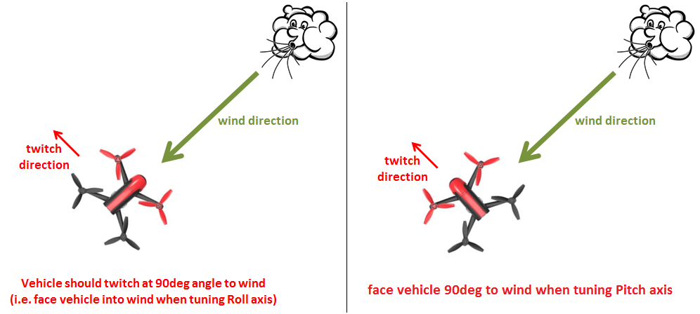
Face the vehicle so that it will twitch at 90° from the direction the wind is blowing (i.e. if tuning Roll first, point the vehicle into the wind)
Set Switch B to HIGH to engage auto tuning
You will see it twitch about 20 degrees left and right for a few minutes, then it will repeat forward and back.
Open messages in the QGroundControl/Mission Planner to see the Autotune messages
Use the roll and pitch stick at any time to reposition the copter if it drifts away (it will use the original PID gains during repositioning and between tests). When you release the sticks it will continue auto tuning where it left off.
Set Switch B LOW position at any time to abandon the autotuning and return to the origin PIDs.
Make sure that you do not have any trim set on your transmitter or the autotune may not get the signal that the sticks are centered.
When the tune completes the copter will change back to the original PIDs.
Set Switch B to LOW then to HIGH to test the tuned PIDs.
Set Switch B to LOW to fly using the original PIDs.
If you are happy with the autotuned PIDs, set Switch B to HIGH position, land and disarm to save the PIDs permanently.
If you DO NOT like the new PIDS, set Switch B to LOW. The autotune PIDs will not be saved when you disarm.
Set AUTOTUNE_AXES to the next axis and repeat 1-10.
Note
If the vehicle will not start tuning (i.e. it won’t twitch) even though it is in AutoTune mode then the problem is likely that the roll, pitch, yaw or throttle sticks are not exactly in the middle. It may help to increase the deadzone on the RC input by increasing RC1_DZ, RC2_DZ, RC3_DZ and RC4_DZ to 50 (or higher).
If the AutoTune produces an overly twitchy vehicle try reducing the AUTOTUNE_AGGR parameter (should never be below 0.05) and perform the AutoTune again.
If the AutoTune produces a sloppy vehicle, try increasing the AUTOTUNE_AGGR parameter (should never be above 0.1) and perform the AutoTune again.
Load Configuration
If you change a parameter which results in unexpected results it is easiest to revert it back to the default configuration. Not much should need changing from this default configuration. It even saves the previous compass and accelerometer calibrations.
QGroundControl
Download the
params fileNavigate to Vehicle Setup > Parameters > Tools > Load from file…
Select AquaCopterQGC.params
Select Ok to load parameters
Mission Planner
Download the
params fileNavigate CONFIG > Full Parameter Tree >:guilabel:Load from file
Select AquaCopterMP.param
Select Write Params
Reboot Copter
You need to reboot the copter after doing a sensor calibration (accelerometer/compass). Most of the times there is a popup which allows you to do this. To invoke manually, disconnect and reconnect the battery. It can also be done in the ground station
QGroundControl
Navigate to Vehicle Setup > Parameters > Tools > Reboot Vehicle
Mission Planner
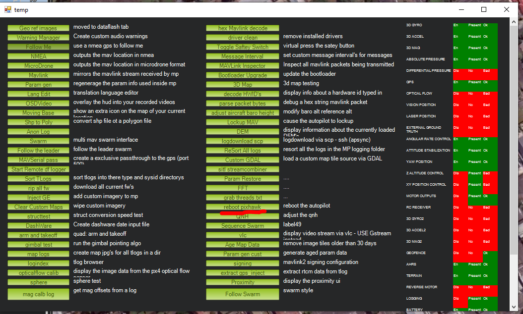
While in Mission Planner, press CTRL+F on your keyboard, a window should popup called temp
Select reboot pixhawk
ESC Calibration
This only needs to be done when a new ESC is attached to the copter. The Pixhawk talks to the ESC to get the minimum and maximum signal values.
Remove Propellers
Remove power
Power on. There will be multiple tones
Once tones have finished, disconnect battery and power up again
Charging Batteries
We use the iMax B6AC to charge the batteries. It can charge/discharge LiPo, Li-Ion, LiFe, NiCd, NiMH, and Pb batteries. The copter batteries are LiPo chemistry. They have a high-power density and high discharge rate.
Safety
They are the most dangerous rechargeable battery chemistry. Each cell should be between 3V-4.2V. The load should not exceed 20C ≈ 100A. If these limits are exceeded, it will permanently damage the battery. In worse cases it can smoke and catch fire. The fumes are not good for you. The fire is self-oxidizing thus must be smothered with sand or like to stop fire.
Only charge batteries in the shed. Never inside
Inspect the battery before use. If the battery is punctured, puffy, or bulging, do not charge
Balance Charging Setup
Plug charge into power
Connect balance lead
Connect XT90
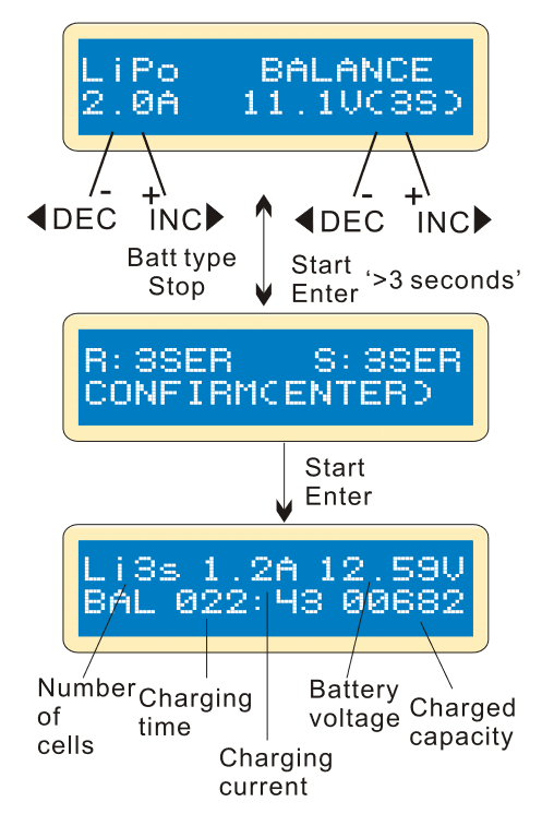
Use BATT/PROG and DEC buttons to navigate to PROGRAM SELECT LiPo BATT. Press ENTER button
Use INC and DEC buttons to navigate to LiPo BALANCE. Current should be 2A and voltage should be 22.2V(6S). To change values, single press ENTER and select the correct current/voltage.
Hold down ENTER for 3 seconds. A confirmation screen should show R: 6SER S: 6SER. This means 6 cells are connected to the charger. Single press ENTER to continue
This screen shows the live values during the charging process. It can be stopped with the BATT TYPE/STOP button. The charger will beep once finished
Fast Charge
One should use this feature only when necessary. Balance charge ensures each cell is evenly charged resulting in a slightly higher capacity and longer battery life. Follow the balance charging setup. It should take a fully discharged battery 30mins to charge compared to 1h30min on balance charge
- Current
5A
- Voltage
22.2V(6S)
Storage
Battery should be charged a few days before use. At other times the battery should be set a storage voltage. This improves the battery life.
- Current
1A
- Voltage
22.2V(6S)
Discharge Test
This can be used to test the capacity of the battery.
- Current
1A
- Voltage
22.2V(6S)
Disposing Old Batteries
Old batteries still have enough energy to catch fire thus must be discharged to 0V before disposing. This can be done with power resistors or LED. Many NZ hobby shops sell, “Lipo Killers”. All these need adapters from XT90 to XT60